Electrical Design
Fritzing Diagram
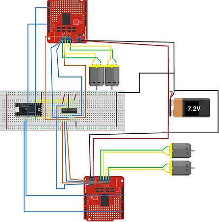
Arduino Teensy LC
Shift Register
Vex Motor 393 (x4)
7.2 NiMH Battery
L298N Motor Driver (x2)
The "Brains"
While designing the electrical system of our robot, we wanted it to be as simple as possible to allow us to test quicker and find problems easier. This started with figuring out how to create the robot's "Brains." All of our WARRIOR's movement, sensing and control is managed by a single Arduino Teensy LC. This Arduino was powered off a 5V line from one of our L298N motor drivers. However, using just one Arduino would not be possible without the inclusion of a shift register.
A shift register is a type of sequential logic circuit commonly used for data storage or data movement. They are made up of smaller parts called 'flip-flops' that each control one bit, move between 0 and 1 states, and are all connected to the same clock. The 'flip-flops' are connected so that output is the input of one so on each clock pulse, the shift register's contents shift either left or right by one bit.
Ultimately, what this allows us to do is control multiple outputs from the shift register. Our 8-bit, SIPO (Serial-In-Parallel-Out) shift register controlled eight separate outputs while only requiring three inputs from the Arduino. This minimized the number of pins we needed to use in our Arduino as well as allowed for neater wiring. Connecting all the motor driver outputs alone directly to the Arduino required 8 I/O pins, but using the shift register minimized this to just 3 I/O pins subsequently increasing the number of I/O pins that could connect other components.
Sensing
There were several available sensors that could have been implemented such as:
-
IR sensors to sense the IR beacons mounted on two of the towers and the Dragon
-
Tape sensors for the robot to follow the black tape in the arena to get from the Throne Room to the Armoury
-
Ultrasonic sensors to detect the wall
-
Limit switches for contact detection
We initially wanted to implement IR sensors but were not able to amplify the signal enough and were spending too much time on it that it began to detract from working on other parts of the robot. Thus, we went without it. Tape sensors were not needed since our strategy required not following marked lines on the arena but rather the walls. This left us to decide between ultrasonic sensors and limit switches.
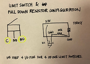
We opted to use four limit switches, one on each side of the robot, because they were much easier to integrate mechanically and electronically. The “normally closed” (NC) terminal of the limit switch was connected to the 3.3V source of the Teensy, while the “common” (C) terminal was connected to an Arduino pin, which was then connected to a 10kΩ pull down resistor (i.e. connected to ground on the other end). We chose to use the NC and C terminal such that the Arduino would always read a high input until the limit switch was pressed (i.e. circuit is always closed until limit switch is pressed, causing the circuit to open), and would then read a low input instead.
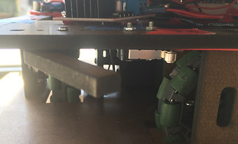

Each limit switch used was triggered by a bumper, so that it was not the limit switch itself that was being hit, and possible damaged, whenever the robot made contact with a wall. The above left image shows what the limit switch looks like under the bumper while the above center image shows the initial position of the bumper and limit switch before hitting a wall. These switches and bumpers were positioned well above the ground in prevent any debris that the robot ran into from triggering the sensors.
Power
We chose the Vex 2-wire motor 393 as our robot's main motors for movement for two main reasons. First, they were the only available motors that integrated with the square shaft required for the omni-wheels without the need to jury-rig a shaft adapter. Second, they only needed 7.2V for operation compared to the 12V that many other motors required. This allowed us to use one NiMH battery at a time, reducing weight and eliminating any lost time to recharge batteries.
Two pairs of Vex motors were connected to two L298N motor drivers which are capable of running motors from 5V to 35V as well as possessed large heat sinks which mitigated any overheating problems. Furthermore, these drivers had a separate 5V output that we used to power the rails of our breadboard, and subsequently our Arduino and other components, with 5V.
To shoot our ammunition, the turret's flywheel was run with a 5V DC motor. However, we needed to power a 5V DC motor with control, which meant operating it with a MOSFET. To implement this, we used a simple boost converter to bump the 7.2V up to approximately 10V, from which we were able to operate the N-Channel MOSFET in the linear region with a simple PWM signal to provide the precise power needed to accurately hit the targets. An added benefit of this design was that as the battery’s voltage dropped, there was no worry that the flywheel would lose power and that our robot would, as a result, lose its ability to shoot accurately, if not entirely. As the boost converter provides a stable output with input voltages as low as 3V, its addition meant that battery charge was never a true issue.
For the gate in the turret's ramp that held the ammo back until the WARRIOR was ready to fire, we attached an arm to a small Servo motor (Tower Pro SG90), and connected it to our Teensy microcontroller. This gate servo was powered from the 5V rail on the breadboard, which came from the 5V outputs of the motor drivers, and removed the need for a separate 5V regulator.
The turret servo was significantly heftier, as it needed to be able to swing the entire shooting apparatus around with reasonable speed. This servo was the DS3218MG 20kg servo which requires 4.8-6.8V and was powered by the same 5V supply from the motor drivers.
Power to the entire robot is controlled by an external switch that can cut all power to the machine when toggled off.