Mechanical Design
Initial Designs


The majority of the initial design process revolved around how to hold and fire the ammunition. One idea involved using a rotating barrel to hold ammo and drop it into an angled pipe with a single vertical flywheel. Another involved a vertical ammo holder and two sets of horizontal flywheel, the first shuffles the ammo forward to the next set which fires it.
Final Design


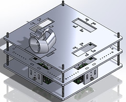
CAD model of our final design displaying chassis, powertrain, and launcher but excluding electronics, wiring, and other non-fabricated components. (Clockwise from bottom left: Front View, Top View, Exploded View, Isometric View, Right View)


The final design ultimately ended up being quite different from the initial concepts because they were only capable of firing forwards. In order to hit multiple towers quickly, a turret system attached to the top of the robot was created. It substantially decreases the time that would be required to move into multiple positions to fire straight at towers. Instead, our WARRIOR can take up one position and only rotate its launcher to hit multiple towers.
To keep the turret as light as possible, ammo was held in a cardboard ramp that was curved in order to meet the 12"x12"x12" size specifications.
The robot's movement is created by an arrangement of four omni-directional wheels which can rotate in one dimension and translate in another. Effectively, this allows it to move at 90 degree angles, eliminating the need to turn.
Our fully constructed WARRIOR, Dim Sum, finished with check-off and ready for competition
Chassis

The chassis was deliberately arranged into three tiers that hold separate robot subsystems:
-
Bottom- Powertrain (motors and drivetrain)
-
Middle - The "Brains", sensors, and most of the circuitry and electrical components
-
Top - Turret system
Each tier was made of 1/4" thick duron cut into 11.50"x11.50" squares to ensure the robot is within size constraints. Fillets were applied to each edge to prevent robot from getting stuck in corners while threaded rods were included to give more structural stability. Although it may not be the prettiest or most complex chassis, its simplicity allowed for rapid prototyping and modifications. The square shape is not only ideal for the desired 90 degree movement but also maximizes the area available for components.
Drivetrain


The drivetrain (the components that deliver power to the wheels) is comprised of a set of three shaft collars and two pillow block bearings around a square shaft connected to a motor.
This arrangement is used for each wheel and can be seen in the above left image. The order from motor outwards is: pillow block - shaft collar - omniwheel - shaft collar - pillow block - shaft collar.
Turret


The turret represents a combination of mechanical electrical and software design. And because of this, integrating all of these facets correctly required many hours of calibration.
The turret's launcher was completely 3D printed to give us a consistent launch angle and affixed at its base to a high-torque servo motor that was coded to rotate at pre-determined angles to face the opposing towers.
Attached to the launcher is the flywheel, a foam wheel run by a high-torque 5V motor that could launch our ammo with enough force to knock over all the towers. Control of this flywheel was done through a N-Channel MOSFET as well as a boost converter that could alter the amount of voltage running through the flywheel to adjust how far it fired.
And finally, the ramp which held all the ammo was made out of cardboard to ultimately reduce the load on the servo that rotated the whole turret. It was angled enough so that the ammo would roll into the launcher when the gate, a small servo with an arm glued to it, at the bottom of the ramp opened.
Our turret proved to be quite a success during testing and check-off. It was accurate and reliable, earning praise from Professor Gumerlock in the process. But as great as it performed, we would still liked to improve its build quality if we had more time.